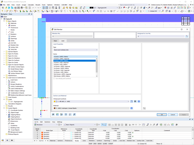
The "Virtual Joist" member type allows you to simulate prefabricated beams in a global model. The beam is replaced by a member with a virtual section.
This function makes it easier for you to simulate complex supporting units, such as a truss girder, in the overall system.

Can you use some support? The "surface model" member type helps you to simulate a member as a surface model in the overall model.
This feature provides you with the following:
- Quick input using a member with a cross-section
- Simulation of openings in the web
- Simultaneous output of the member and surface results
- Design of member results in the add-on
- Consideration of a real stress distribution
You can use the surface member for the following applications, among others:
- Castellated beams
- Perforated beams
- Beams with rectangular openings
- Vierendeel trusses

- Many predefined components available for easy input of typical connection situations (for example, end plates, cleats, fin plates)
- Universally applicable basic components (plates, welds, bolts, auxiliary planes) for entering complex connection situations
- Graphical display of the connection geometry that is updated in parallel with the input
- The Steel Joints Template included in the Add-on allows you to select from several connection types and, when selected, is applied to your model
- In the Template, there are connections from 3 general categories: Rigid, Pinned, Truss
- Automatic adaptation of the connection geometry, even if the members are subsequently edited, due to the relative relation of the components to each other
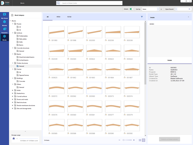
Are you looking for models for your design? Then you have come to the right place at the Dlubal Center. It contains an extensive database with partly parameterized models. These include, for example, trusses, glulam beams, tapered frames, or tower segments. You can import these models and, if necessary, modify them according to your individual requirements. Furthermore, you can save the models as a block for later use.
_ENG.png?mw=640&hash=1053c9bef400e9f5361c9c3278f76a272fcc4ddf)
Have you activated the Time-Dependent Analysis (TDA) add-on? Very well, now you can add time data to load cases. After you have defined the start and end of the load, the influence of creep at the end of the load is taken into account. The program allows you to model creep effects for frame and truss structures made of reinforced concrete.
In this case, the calculation is performed nonlinearly according to the rheological model (Kelvin and Maxwell model).
Was the calculation successful? You can now display the determined internal forces in tables and graphics, and consider them in the design.
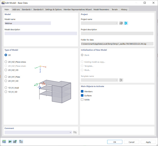
There are many options available for simple input and modeling. Your model is entered as a 1D, 2D, or 3D model. Member types such as beams, trusses, or tension members make it easier for you to define member properties. In order to model surfaces, RFEM provides you with various types, such as Standard, Without Thickness, Rigid, Membrane, and Load Distribution.
Furthermore, RFEM covers various material models, such as Isotropic | Linear Elastic, Orthotropic | Linear Elastic (Surfaces, Solids), or Isotropic | Timber | Linear Elastic (Members).
.png?mw=640&hash=9aa98962d5e0d0ed2803b35fcb6a2f87288b0946)
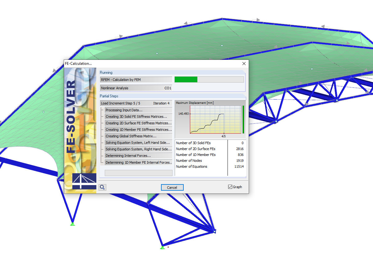
The number of degrees of freedom in a node is no longer a global calculation parameter in RFEM (6 degrees of freedom for each mesh node in 3D models, 7 degrees of freedom for the warping torsion analysis). Thus, each node is generally considered with a different number of degrees of freedom, which leads to a variable number of equations in the calculation.
This modification speeds up the calculation, especially for models where a significant reduction of the system could be achieved (for example, trusses and membrane structures).
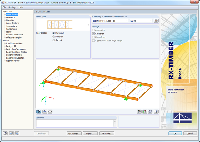
The geometry is entered by means of templates, as in all other programs of the RX‑TIMBER family. By selecting the roof structure, you define the base geometry, which can be adjusted by user-defined settings. The relevant timber grade of the material can be selected from the material library. All material grades for glulam, hardwood, poplar and softwood timber specified in EN 1995-1-1 are available. Furthermore, it is possible to generate a strength class with user-defined material properties in order to extend the library.
Since the stiffening bracing includes the steel cross-sections, current steel grades are integrated in the library as well. Therefore, rolled and welded cross-sections are also available. Stiffening of coupling elements can be considered in Table 1.5 Connections as translational and rotational spring stiffnesses. The program handles these stiffnesses with a stiffness divided by the partial safety factor for the design of the bearing capacity and with the mean values of the stiffness for the serviceability limit state design. The loading can be entered directly as a lateral load (equivalent lateral load) resulting from a truss girder design.
The wind load is applied automatically to all four sides of the structure. Additionally, you can specify user-defined loads; for example, concentrated loads from columns (buckling load). According to the generated loads, the program automatically creates combinations for the ultimate and serviceability limit states as well as for fire resistance design in the background. The generated combinations can be considered or adjusted by user-defined specifications.
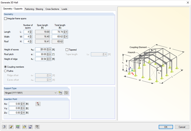
Generating tools to enter parametric models such as frames, halls, trusses, spiral stairways, arcs, or roofs. In addition, many generators allow for the creation of load cases and loading resulting from weight, snow, and wind.
- Integration in RFEM/RSTAB with automatic geometry recognition and transfer of internal forces
- Optional manual definition of connections
- Extensive library of hollow sections for chords and struts:
- Round sections
- Square sections
- Rectangular sections
- Implemented steel grades: S 235, S 275, S 355, S 420, S 450, and S 460
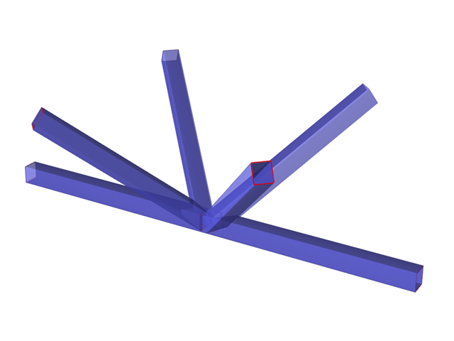
- Various types of connections available, depending on the standard specifications:
- K connection (gap/overlapping)
- KK connection (spatial)
- N connection (gap/overlapping)
- KT connection (gap/overlapping)
- DK connection (gap/overlapping)
- T connection (planar)
- TT connection (spatial)
- Y connection (planar)
- X connection (planar)
- XX connection (spatial)
- Selection of partial safety factors according to the National Annex for Germany, Austria, Czech Republic, Slovakia, Poland, Slovenia, Switzerland, or Denmark
- Adjustable angles between struts and chords
- Optional chord rotation of 90° for rectangular hollow sections
- Consideration of gaps between struts or overlapping struts
- Optional consideration of additional nodal forces
- Design of the connection as the maximum load-bearing capacity of the struts of a truss for axial forces and bending moments
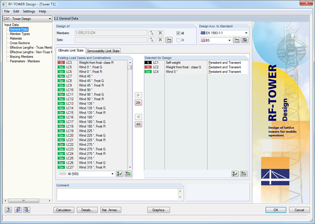
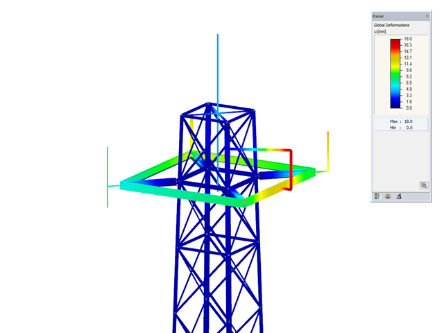
Members of triangular and quadrilateral lattice towers are allocated automatically, provided that the lattice tower was generated in the RF-/TOWER Structure and RF-/TOWER Equipment add-on modules.
However, it is also possible to allocate the members manually. In RF-/TOWER Design, you can use the effective lengths of truss members generated in the RF-/TOWER Effective Lengths add-on module. Manual input is also possible.
According to the EN 1993-3-1 and EN 50341 standards, different bracing cases and support types can be specified for the leg members and bracing members.
- Consideration of the data from the other RF-/TOWER modules (Structure, Equipment, Loading, Effective Lengths)
- Automatic cross-section classification
- Design of triangular and quadrilateral lattice towers according to EN 1993-1-1, EN 1993-3-1, and EN 50341, including National Annexes
- Flexural buckling analysis of truss members based on the effective slenderness considering bracing and support conditions
- Design of equipment such as platforms according to EN 1993-1-1
- Clearly arranged display of results including relevant parameters in result tables
- Parts list result window
- Creation of a verifiable printout report
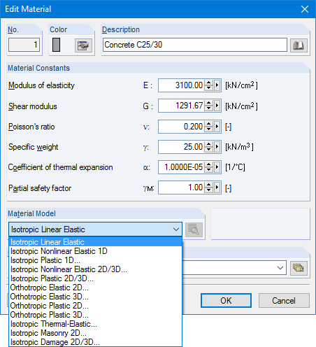
Structures are entered as 1D, 2D, or 3D models. Member types such as beams, trusses, or tension members facilitate the definition of member properties. For modeling surfaces, RFEM provides For example, the types Standard, Orthotropic, Glass, Laminate, Rigid, Membrane, and so on, are available.
Furthermore, RFEM can select among the material models Isotropic Linear Elastic, Isotropic Plastic 1D/2D/3D, Isotropic Nonlinear Elastic 1D/2D/3D, Orthotropic Elastic 2D/3D, Orthotropic Plastic 2D/3D (Tsai-Wu 2D/3D), and Isotropic Thermal -elastic, Isotropic Masonry 2D, and Isotropic Damage 2D/3D.